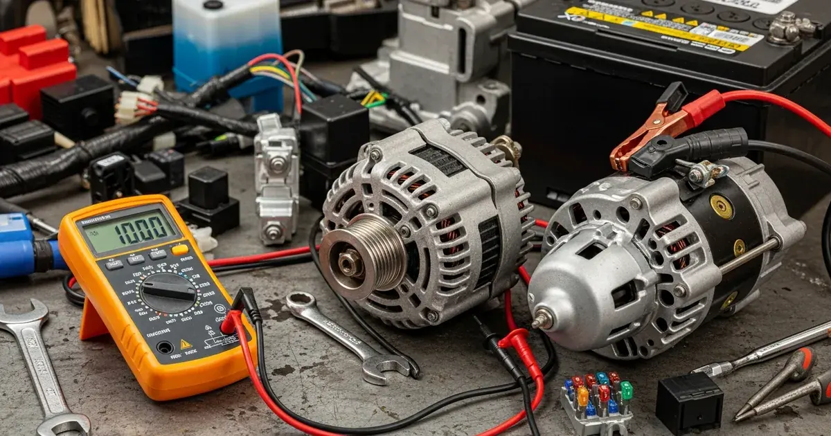
The charging and starting systems are the foundation of every truck's electrical system. When the alternator fails, the truck runs on battery power alone — and in a modern truck with electronic engine controls, ELD, air conditioning, and lighting systems drawing power, the batteries may last only a few hours before the truck shuts down. When the starter fails, the truck simply will not start. Systematic diagnosis of these systems saves time and money by identifying the actual failed component rather than replacing parts through guesswork.
Understanding the Charging System
The charging system consists of the alternator, voltage regulator, battery isolator (in dual-battery systems), wiring harness, and batteries. The alternator converts mechanical energy from the engine into electrical energy through electromagnetic induction. The voltage regulator controls the alternator's output to maintain system voltage between 13.8 and 14.4 volts. The battery isolator ensures that both batteries charge equally while preventing one failed battery from draining the other.
In modern trucks, the voltage regulator is often integrated into the engine's ECM rather than being a separate component on the alternator. This integration allows the ECM to manage charging based on battery state of charge, electrical load demand, and engine operating conditions. While this provides more precise charging control, it also means that charging system problems may be caused by ECM software issues rather than alternator hardware failures.
Alternator Output Testing
Proper alternator testing requires both voltage and amperage output measurement. Voltage testing alone is insufficient because an alternator can maintain correct voltage while producing inadequate current to support the truck's electrical loads.
To test voltage output, connect a multimeter across the battery terminals with the engine running at idle. The reading should be 13.8 to 14.4 volts. Increase engine speed to 1,500 RPM — voltage should remain stable. Turn on all electrical loads (headlights, HVAC blower, marker lights) — voltage should not drop below 13.5 volts under load. If voltage drops below 13 volts under load, the alternator is not producing sufficient output.
Amperage output testing requires a clamp-on ammeter placed around the alternator output wire. With all loads on and the engine at operating speed, the alternator should produce close to its rated amperage output. A 160-amp alternator should produce at least 130 to 140 amps under full load. If output is significantly below rated capacity, the alternator has internal problems — worn brushes, failed diodes, or damaged stator windings.
Diode Failure Diagnosis
The alternator produces alternating current internally, which is converted to direct current by a set of diodes in the rectifier bridge. When one or more diodes fail, the alternator's output is reduced because the affected phase of the stator is no longer contributing to the output. A single failed diode typically reduces output by approximately one-third.
Diode failure produces a distinctive symptom: the alternator appears to work — it produces voltage — but it cannot keep up with the electrical load. The batteries slowly discharge over the course of a driving day, and the driver may notice gradually dimming lights or sluggish starter cranking at the next start attempt.
An oscilloscope connected to the alternator output provides a definitive diode failure diagnosis. A healthy alternator produces a smooth ripple pattern. A failed diode creates a visible gap in the ripple pattern where the dead phase should be contributing. Without an oscilloscope, a sharp increase in AC voltage measured at the battery terminals (more than 0.5 volts AC with the engine running) also indicates diode failure.
Parasitic Draw and the Charging System
A parasitic draw is an electrical load that continues to drain the batteries when the truck is shut off. Normal parasitic draw for a modern truck is 50 to 85 milliamps — enough to maintain ECM memory, ELD standby, and clock functions. Draws exceeding 100 milliamps will noticeably affect battery state of charge overnight, and draws above 200 milliamps can kill batteries in a few hours.
Excessive parasitic draw often masquerades as an alternator problem. The driver reports dead batteries and assumes the alternator is not charging, when in reality the alternator is fine but a hidden electrical load is draining the batteries faster than the alternator can recharge them during driving. Always check for parasitic draw before condemning an alternator.
Starter Motor Diagnosis
The starter motor is a high-torque DC motor that cranks the engine for starting. Commercial truck starters must turn a large diesel engine against high compression — they draw 200 to 400 amps during cranking. This enormous current draw demands that batteries, cables, and connections all be in excellent condition.
When the starter fails to crank the engine, begin diagnosis at the batteries. Load test both batteries individually. A single weak battery in a dual-battery system can prevent starting even if the other battery is good because the weak battery acts as a load on the good battery. Replace batteries as a set in dual-battery installations.
If the batteries test good, check the battery cables and connections. Measure voltage drop across each cable connection during cranking. Place the multimeter positive lead on the battery positive terminal and the negative lead on the starter terminal. Crank the engine — the voltage drop should be less than 0.5 volts. A higher drop indicates a high-resistance connection that is stealing voltage from the starter. Clean and tighten all connections and retest.
If batteries and cables are good but the starter does not engage, the starter solenoid may have failed. The solenoid is the electromagnetic switch that engages the starter gear with the flywheel and connects battery power to the starter motor. A clicking sound without cranking typically indicates a solenoid that is trying to engage but lacking sufficient power to hold the contacts closed — usually caused by low voltage from weak batteries or poor connections.
A starter that cranks slowly indicates either weak batteries, high-resistance connections, or a worn starter motor with internal friction or short circuits. Measure the starter draw with a clamp-on ammeter during cranking. Current draw significantly above the specification for your starter model indicates internal problems requiring starter rebuild or replacement.
Battery Isolator Problems
The battery isolator in dual-battery systems ensures that both batteries charge from the alternator while remaining electrically isolated during starting and shutdown. When the isolator fails, one battery may not charge, or both batteries may drain through the failed isolator when the engine is off.
Test the isolator by measuring voltage at each battery with the engine running. Both batteries should show equal charging voltage within 0.2 volts. If one battery shows significantly lower voltage, the isolator's solenoid or diode for that circuit may have failed. Some isolators are controlled by the ECM and may require diagnostic scanner testing to verify proper operation.
For professional electrical and lighting system diagnosis and mobile repair, call Weldon's Truck & Trailer at (334) 759-7020. Our technicians carry diagnostic equipment for all major truck electrical systems and can perform alternator, starter, and charging system service at your location.